
I'm starting work on a interface to retain the factory steering wheel mounted cruise control buttons for @LBarr2002 's LS Swapped LJ.
What the Jeep Has -
The jeep uses a pretty common multiplexed signal system to allow multiple buttons to share just two signal paths. The reason for this is basically a cheaper simple clock spring. How it works is all of the buttons share a common connection all in parallel with each other, just with different resister values being connected.
Basically like this....
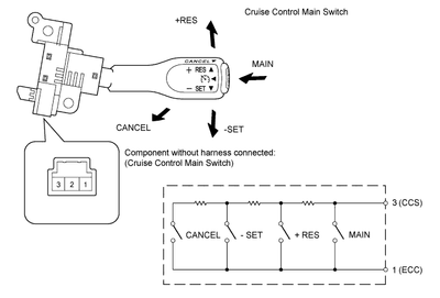
We have located the signals and removed them from the factor harness, I have quickly verified that it operates as others claim it does. I have yet to measure the values for each button press but here are the values I have come across online.
------ 1998 ------ 2001
None-- Open --- 19K
On --- 920 --- 440
Set --- 6.6K --- 4.1K
Res --- 15K --- 8.35K
Coast - 3K --- 2.5K
Cancel-- 0K --- 1.15K
What the GM Harness Looks for - (Taken from http://lt1swap.com/dbw.htm )
Cruise Set/Coast Signal - This is a momentary switch signal which sends 12v+ down this wire. Momentary meaning, it only sends 12v+ when the switch is pressed, when you release the switch, it should turn off. Pressing this switch quickly will set the current speed and it will be maintained. Holding it on will let vehicle coast, when you release, that will be the new set speed to be maintained. After set, each quick press of the switch will lower set speed 1 mph.
Cruise On Signal - This is simply an on / off switch that enables or disables the cruise function. This needs to be switched 12v+ to this wire.
Cruise Resume/Accel Signal - This is a momentary switch signal which sends 12v+ down this wire. Momentary meaning, it only sends 12v+ when the switch is pressed, when you release the switch, it should turn off. This switch ONLY functions after you have previously pressed the SET/COAST switch. Resume will resume vehicle speed after hitting the brakes. Holding this switch will make vehicle accelerate until you release it. Each quick press of the switch will increase set speed 1 mph.
Stop Lamp Supply Voltage - This wire should be hooked to the same wire that feeds you're brake lights 12v+ when you press on the brake pedal. The TAC module checks this circuit by monitoring lamp bulb resistance to ground. So cruise will not function if you try to use LED bulbs, or a simple on/off switch for this signal. THIS IS NOT THE SAME WIRE AS TCC BRAKE SWITCH THAT THE PCM USES TO UNLOCK TORQUE CONVERTER.
After those are wired, you also MUST have the TCC brake switch signal to the PCM. If this signal is not received by the PCM, cruise will not function. TCC Brake Switch Signal is 12v+ when brakes are NOT pressed, and the switch OPENS when you hit the brakes. This signal wire is at PCM connector C1-Blue: Pin #33; Purple wire.
My Solution
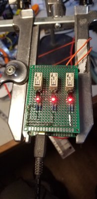
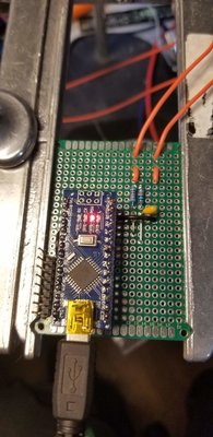
My plan is to use a simple microprocessor fed by a voltage divider and driving a couple signal relays. Ive been developing test fixtures and other random gadgets with Arduino and Microchip Processors for over 5 years and have been writing code for more than 10 years, so this seems like a pretty straight forward project. I sketched up a basic schematic {by no means enough info to directly copy this design, yet} for reference and dug through my boxes of parts to see what I had around. I buy "knockoff" Arduino Nano boards in bulk, so i choose to use one of those for the design, I also decided to socket it to the lower board, just in case i need to swap it out at some point. When this is all built up, i will either drop it in a bud box or 3D Print a housing.
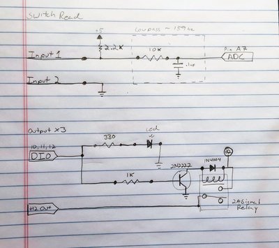
This is what i have come up with so far. Couple hours of work, extra detail in making it look good for the internet.
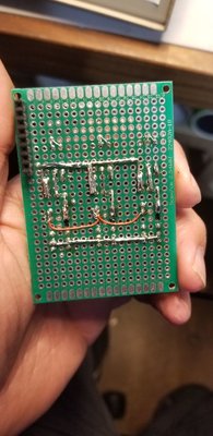
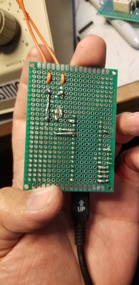
Still deciding on a good rugged Voltage regulator to use to power the micro, I have some regulators with supervisor circuits built in, probably use one of those with some extra diodes added for good measure.
Now on to the software.
What the Jeep Has -
The jeep uses a pretty common multiplexed signal system to allow multiple buttons to share just two signal paths. The reason for this is basically a cheaper simple clock spring. How it works is all of the buttons share a common connection all in parallel with each other, just with different resister values being connected.
Basically like this....
We have located the signals and removed them from the factor harness, I have quickly verified that it operates as others claim it does. I have yet to measure the values for each button press but here are the values I have come across online.
------ 1998 ------ 2001
None-- Open --- 19K
On --- 920 --- 440
Set --- 6.6K --- 4.1K
Res --- 15K --- 8.35K
Coast - 3K --- 2.5K
Cancel-- 0K --- 1.15K
What the GM Harness Looks for - (Taken from http://lt1swap.com/dbw.htm )
Cruise Set/Coast Signal - This is a momentary switch signal which sends 12v+ down this wire. Momentary meaning, it only sends 12v+ when the switch is pressed, when you release the switch, it should turn off. Pressing this switch quickly will set the current speed and it will be maintained. Holding it on will let vehicle coast, when you release, that will be the new set speed to be maintained. After set, each quick press of the switch will lower set speed 1 mph.
Cruise On Signal - This is simply an on / off switch that enables or disables the cruise function. This needs to be switched 12v+ to this wire.
Cruise Resume/Accel Signal - This is a momentary switch signal which sends 12v+ down this wire. Momentary meaning, it only sends 12v+ when the switch is pressed, when you release the switch, it should turn off. This switch ONLY functions after you have previously pressed the SET/COAST switch. Resume will resume vehicle speed after hitting the brakes. Holding this switch will make vehicle accelerate until you release it. Each quick press of the switch will increase set speed 1 mph.
Stop Lamp Supply Voltage - This wire should be hooked to the same wire that feeds you're brake lights 12v+ when you press on the brake pedal. The TAC module checks this circuit by monitoring lamp bulb resistance to ground. So cruise will not function if you try to use LED bulbs, or a simple on/off switch for this signal. THIS IS NOT THE SAME WIRE AS TCC BRAKE SWITCH THAT THE PCM USES TO UNLOCK TORQUE CONVERTER.
After those are wired, you also MUST have the TCC brake switch signal to the PCM. If this signal is not received by the PCM, cruise will not function. TCC Brake Switch Signal is 12v+ when brakes are NOT pressed, and the switch OPENS when you hit the brakes. This signal wire is at PCM connector C1-Blue: Pin #33; Purple wire.
My Solution
My plan is to use a simple microprocessor fed by a voltage divider and driving a couple signal relays. Ive been developing test fixtures and other random gadgets with Arduino and Microchip Processors for over 5 years and have been writing code for more than 10 years, so this seems like a pretty straight forward project. I sketched up a basic schematic {by no means enough info to directly copy this design, yet} for reference and dug through my boxes of parts to see what I had around. I buy "knockoff" Arduino Nano boards in bulk, so i choose to use one of those for the design, I also decided to socket it to the lower board, just in case i need to swap it out at some point. When this is all built up, i will either drop it in a bud box or 3D Print a housing.
This is what i have come up with so far. Couple hours of work, extra detail in making it look good for the internet.
Still deciding on a good rugged Voltage regulator to use to power the micro, I have some regulators with supervisor circuits built in, probably use one of those with some extra diodes added for good measure.
Now on to the software.